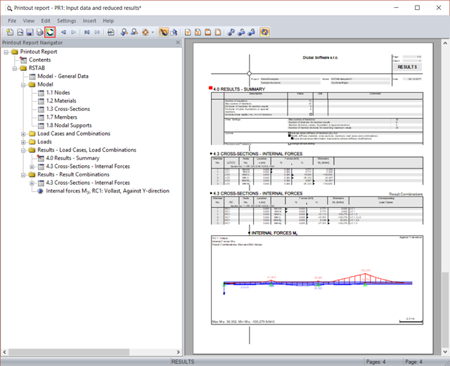
43 Results
View results:
Sort by:

This article describes and explains the influence of bending stiffness of cables on their internal forces. Furthermore, the text provides information on how this influence can be reduced.

Creating a validation example for Computational Fluid Dynamics (CFD) is a critical step in ensuring the accuracy and reliability of simulation results. This process involves comparing the outcomes of CFD simulations with experimental or analytical data from real-world scenarios. The objective is to establish that the CFD model can faithfully replicate the physical phenomena it is intended to simulate. This guide outlines the essential steps in developing a validation example for CFD simulation, from selecting a suitable physical scenario to analyzing and comparing the results. By meticulously following these steps, engineers and researchers can enhance the credibility of their CFD models, paving the way for their effective application in diverse fields such as aerodynamics, aerospace, and environmental studies.

A standard scenario in timber member construction is the ability to connect smaller members by means of bearing on a larger girder member. Additionally, member end conditions may include a similar situation where the beam is bearing on a support type. In either scenario, the beam must be designed to consider the bearing capacity perpendicular to the grain according to NDS 2018 Sec. 3.10.2 and CSA O86:19 Clauses 6.5.6 and 7.5.9. In general structural design software, it is typically not possible to carry out this full design check, as the bearing area is unknown. However, in the new generation RFEM 6 and Timber Design add-on, the added 'design supports' feature now allows users to comply with the NDS and CSA bearing perpendicular to the grain design checks.

The advantage of the RFEM 6 Steel Joints add-on is that you can analyze steel connections using an FE model for which the modeling runs fully automatically in the background. The input of the steel joint components that control the modeling can be done by defining the components manually, or by using the available templates in the library. The latter method is included in a previous Knowledge Base article titled “Defining Steel Joint Components Using the Library". The definition of parameters for the design of steel joints is the topic of the Knowledge Base article “Designing Steel Joints in RFEM 6".

Defining the appropriate effective length is crucial in obtaining the correct member design capacity. For X-bracing that is connected at the center, engineers often wonder if the full end-to-end length of the member shall be used, or whether using half of the length to where the members are connected is sufficient.This article outlines the recommendations given by the AISC and provides an example on how to specify the effective length of the X-braces in RFEM.

This technical article presents some basics for using the Torsional Warping add-on (7 DOF). It is fully integrated into the main program and allows you to consider the cross-section warping when calculating member elements. In combination with the Stability Analysis and Steel Design add-ons, it is possible to perform the lateral-torsional buckling design with internal forces according to the second-order analysis, taking imperfections into account.

The new generation of RFEM software is an intuitive, powerful, and easy-to-handle 3D FEA program that meets all the latest demands in modeling, calculation, and structural design. The modern design concept, as well as the introduction of new features, make the program even more innovative and user-friendly. The main differences between RFEM 6 and its previous version, RFEM 5, are discussed in the following text.
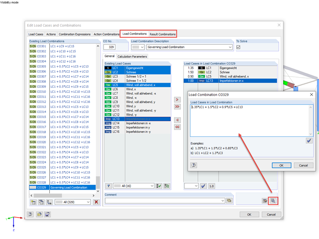
RFEM and RSTAB offer the possibility to edit or check the combinations directly by entering text.
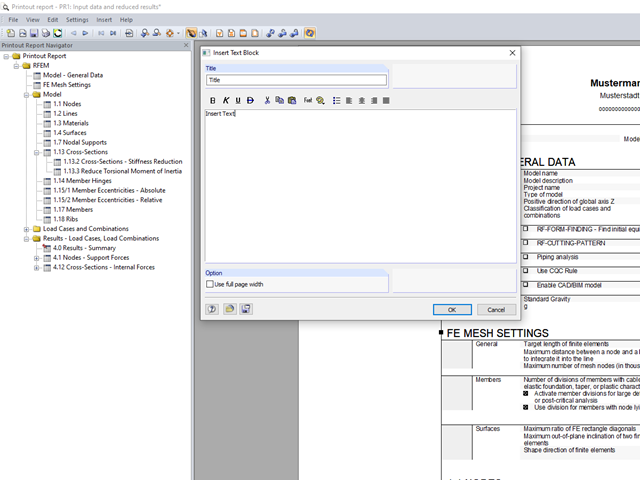
You can insert your own notes in the printout report. To do this, go to the printout report menu and click "Insert" → "Text Block."

You can make various settings in order to achieve a clearly‑arranged display of the result values. For example, some users may not want the white background in text bubbles. You can adjust the background in "Display Properties" using the Transparent and Background color option.
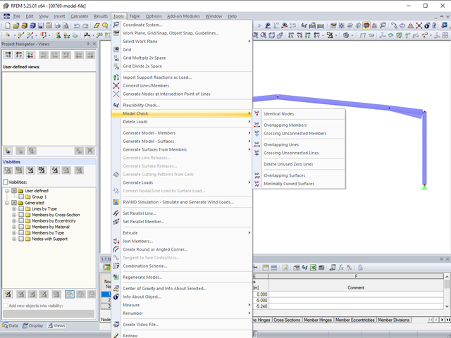
The model check allows you to search for discrepancies occurring during the modeling.

In EN 1993-1-1, the General Method was introduced as a design format for stability analyses that can be applied to planar systems with arbitrary boundary conditions and variable structural height. The design checks can be performed for loading in the main load-bearing plane and simultaneous compression. The stability cases of lateral-torsional buckling and flexural buckling are analyzed from the main supporting plane; that is, about the weak component axis. Therefore, the issue often arises as to how to design, in this context, flexural buckling in the main load-bearing plane.
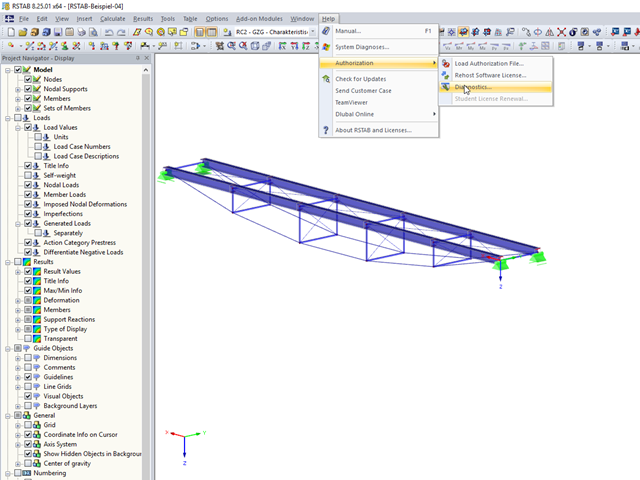
In RFEM 5 and RSTAB 8, you can view detailed information on the currently used license and installed dongle driver. In case of any problems with the license, you can send the created text file to the Dlubal Software hotline, which allows us to provide you with a fast and efficient analysis. To create the file, select "Help" → "Authorization" → "Diagnostics".

In timber design, beams are often built from several timber elements. The individual elements can be connected with glue, nails, bolts, or dowels. A glued connection is to be assumed as rigid. In the case of dowel‑type fasteners, the joint is compliant (slip joint), and the cross‑section properties of the connected elements cannot be fully applied.
.png?mw=640&hash=8fd04a597cecae2e434980ce79fc626815a5d98a)
The Aluminum Design Manual (ADM) 2020 was released in February 2020. The ADM 2020 gives guidance for both the allowable strength design (ASD) and load and resistance factor design (LRFD) for aluminum members to ensure reliability and safety for all aluminum structures. This latest standard was integrated in the RFEM/RSTAB add-on module RF-/ALUMINUM ADM. The text below will highlight the applicable updates relevant to the Dlubal programs.

RFEM 5 allows you to use many different member nonlinearities for designing a model. In the following text, we look at an example of the use of the "slippage" member nonlinearity. The example is a simplified model of a concrete manhole with a square plan view.
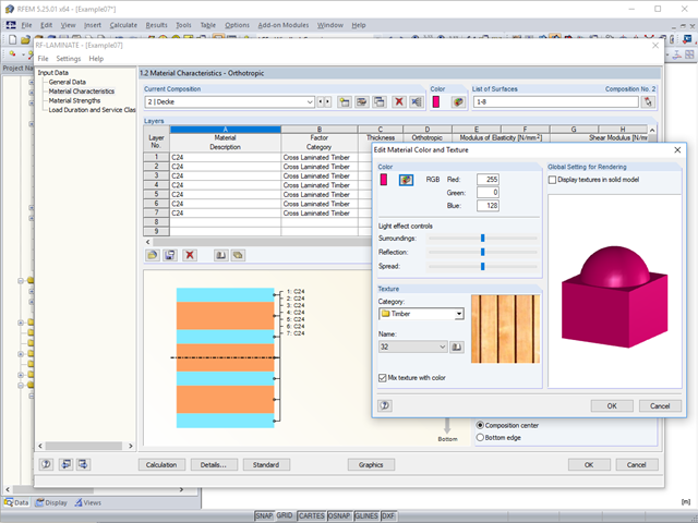
To better distinguish between the different layer compositions (for example, for walls and ceilings), you can assign user‑defined colors and textures to each composition.
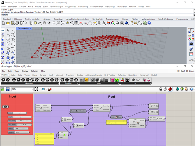
"A good tool is half the job done": This proverb could be applied equally to the software industry. The more a program is task-tailored, the more efficiently the tasks can be solved. The variety and complexity of today's problems, especially in structural engineering, require specifically tailored solutions. Creating your own programs by means of textual programming requires in-depth knowledge and a great ability to abstract. Understandably, only very few engineering offices face this challenge. For this reason, there are additional software solutions providing the user with a visual development environment.

Structures are naturally three-dimensional. However, because it was impossible to perform calculations on three-dimensional models easily in the past, the structures were simplified and broken down into planar subsystems. With the increasing performance of computers and related software, it is often possible to do without these simplifications. Digital trends such as Building Information Modeling (BIM) and new options for creating realistic visualized models reinforce this trend. But do 3D models really offer an advantage, or are we just following a trend? The following text presents some arguments for working in 3D models.

The European standard EN 1993-1-8, Section 4.5.3.3. provides the user with a simplified method for the ultimate limit state design of fillet welds. According to the standard, the design is fulfilled if the design value of the resultant acting on the fillet weld area is smaller than the design value of the weld's load-bearing capacity. Thus, if you want to dimension the weld for a surface model, you will be faced with a variety of results due to the nature of FEM calculations. Therefore, we show in the following text how to determine the force components from the model.
The input windows in RF-/STEEL EC3 distinguish between the flexural and lateral-torsional buckling analyses. In the following text, an example will show the parameters for lateral-torsional buckling.
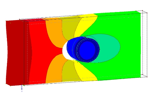
The definition of the non-linear contact problem plays an important role for more detailed investigations of shear/hole bearing connections or their immediate environment. This article uses a solid model to search for comparable and simplified surface models.
The cross-section class of a two-span beam will be designed in the following text. In addition, the necessary cross-section designs will be performed. The global stability failure will be excluded due to sufficient stabilizing measures.
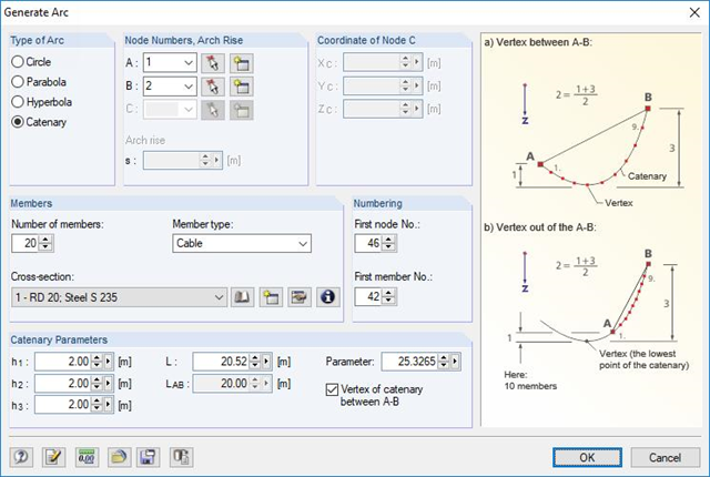
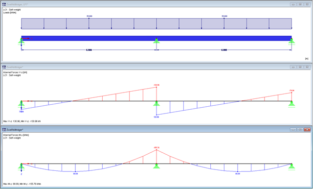
RFEM and RSTAB are able to cover a large number of branches in the building and construction industry with their generally usable structural frame analysis and FEM programs. Designing cable structures is thus also possible in both software solutions. Some assistance tools for modeling and design will be presented in the following text.

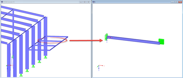
Fin plate connections are a popular form of pinned steel connection and are commonly used for secondary beams in steel structures. They can be used easily in beam structures arranged on the top edge (for example, working platforms). Manufacturing expenditures in the workshop as well as the onsite assembly costs are normally manageable. The design seems to be completed easily and quickly, but it has to be put into perspective to a certain extent in the following text. Moreover, this connection type is basically possible as a pinned beam-to-beam or pinned beam-to-column connection; the former case is the more common one in design practice.
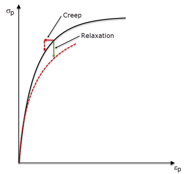
The time-dependent stress losses from creeping, shrinkage, and relaxation have to be considered when designing prestressed concrete components. The consideration of relaxation losses when designing prestressed concrete in RF-TENDON and RF-TENDON Design is discussed in detail in the following text.

Shell buckling is considered to be the most recent and least explored stability issue of structural engineering. This is due less to a lack of research activities than to the complexity of the theory. With the introduction and further development of the finite element method in structural engineering practice, some engineers no longer have to deal with the complicated theory of shell buckling. Evidence of the problems and errors to which this gives rise is very well summarized in [1].
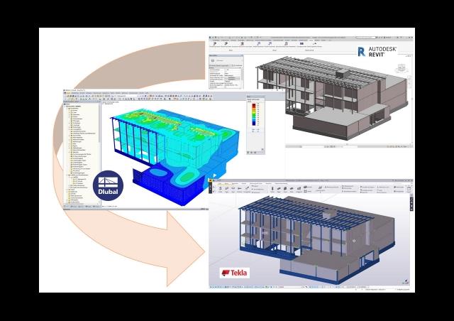
This article discusses the most common BIM interfaces. Adjustments are often necessary during the transition to the structural branch-specific model. The tasks that arise and the tools to address them successfully and quickly are presented.
Printout reports created in RFEM and RSTAB can be transferred to VCmaster using a direct interface and further processed there. VCmaster (formerly BauText) is a word processing program for engineers. Calculations, drawings, photos, and documents from various sources can be easily compiled, managed and used again with VCmaster.

Cable and tensile membrane structures are regarded as very slender and aesthetic building structures. The partly very complex double-curved shapes can be found using suitable form-finding algorithms. One possible solution is to search for the form via the equilibrium between the surface stress (provided prestress and an additional load such as self-weight, pressure, and so on) and the given boundary conditions.